
Circular Tube Section Calculator
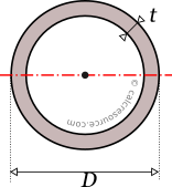
This tool calculates the properties of a circular tube section (also called circular hollow section or CHS). Enter below, the tube diameter D and thickness t. The calculated results will have the same units as your input. Please use consistent units for any input.
D = | |||
t = | |||
Geometric properties: | |||
Area = | |||
Outer circumf. = | |||
Inner circumf. = | |||
Total circumf. = | |||
Properties related to any centroidal axis: | |||
I = | |||
S = | |||
Z = | |||
Rgx = | |||
Iz = | |||
ADVERTISEMENT | |||
 |
ADVERTISEMENT
Definitions
Table of contents
Geometry
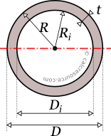
The area A of a circular hollow cross-section, having radius R, and wall thickness t, can be found with the next formula:
where the inner, hollow area radius. In terms of tube diameters, the above formula is equivalent to:
where the inner, hollow area diameter.
Its circumferences, outer and inner, can be found from the respective circumferences of the outer and inner circles of the tubular section. These are:
The total circumferences (inner and outer combined) is then found with the formula:
Moment of Inertia
The moment of inertia (second moment of area) of a circular hollow section, around any axis passing through its centroid, is given by the following expression:
where, , is the outer radius of the section, , is the inner radius and , the wall thickness.
This formula can be deducted, if we consider the circular tube, in the context of moment of inertia calculation, as equivalent to the difference between two solid circular sections: one for the outer circle and the another for the inner circle. For reference, the moment of inertia of a solid circle is: (check our moment of inertia table here).
Expressed in terms of diameters, the moment of inertia of the circular tube can be calculated like this:
where, , is the outer diameter and , is the inner one, which is equal to: .
The dimensions of moment of inertia are .
Flexural bending and moment of inertia
The moment of inertia (second moment or area) is used in beam theory to describe the rigidity of a beam against flexure. The bending moment M, applied to a cross-section, is related with its moment of inertia with the following equation:
where E is the Young's modulus, a property of the material, and the curvature of the beam due to the applied load. Therefore, it can be seen from the former equation, that when a certain bending moment M is applied to a beam cross-section, the resulting curvature is reversely proportional to the moment of inertia I.
Polar moment of inertia
The polar moment of inertia, describes the rigidity of a cross-section against torsional moments, likewise the planar moments of inertia, described above, are related to flexural bending. The calculation of the polar moment of inertia , around an axis z (perpendicular to the section), can be done with the Perpendicular Axes Theorem:
where the and are the moments of inertia around axes x and y, which are mutually perpendicular to z and meet at a common origin. Since, for a circular tube section it is , the above equation becomes:
or in terms of diameters:
Elastic section modulus
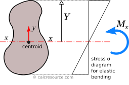
The elastic section modulus of any cross section around an axis x, passing through centroid, describes the response of the section under elastic flexural bending. It is defined as:
where, is the moment of inertia of the section around same axis x, and Y is the distance from centroid of a given section fiber, parallel to the axis x. Typically, the most distant fibers are of special interest, because, they provide the ultimate normal stresses of the cross section, as will be explained right after. Taking into consideration that the most distant fibers, of a circular tube, are indeed points of its outer circumference, their distance, from section center is: . Substitution to the above formula, gives its elastic section modulus, around any centroidal axis, of the circular tube section:
The dimensions of section modulus are .
Elastic modulus and normal stresses
If a bending moment is applied around centroidal axis x, the section will respond with normal stresses, varying linearly with the distance from the axis, assuming the material is linearly elastic and the beam flexural behavior follows the simple beam theory (known as Euler-Bernoulli beam theory). That axis is called elastic neutral axis (or just neutral axis, in short). Over neutral axis, the normal stresses are zero, by definition.
As we move away from neutral axis, normal stresses increase in magnitude, proportionally with distance, as shown in the previous figure. Specifically, the relationship between applied bending moment and normal stresses is given by the formula:
When normal stresses are negative, it means they are compressive, while positive normal stresses are tensile. Therefore, by application of the above formula, positive values result in compressive normal stresses (negative). This is true for the sectional area above the neutral axis, in last figure. The opposite occurs for negative values, which result in tensile stresses (positive). In other words, the entire area below neutral axis is in tension. Take in mind, that this analysis is valid for sagging moment , as indicated in the figure. For a hogging moment, the stresses are inverted, so that tension appears above the neutral axis. The above formula, in that case, is still valid, if we provide a negative sign to any hogging bending moments. Nevertheless, it is quite easy to verify the direction of normal stresses, by inspection alone, rather than rely on sign conventions.
Absolute maximum will occur at the most distant fiber. Taking the (where ), with magnitude given by the formula:
From the last equation, the section modulus can be considered for flexural bending, a property analogous to cross-sectional A, for axial loading. For the latter, the normal stress is F/A.
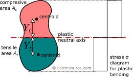
Plastic section modulus
The plastic section modulus is similar to the elastic one, but defined with the assumption of full plastic yielding of the cross section due to flexural bending. In that case the whole section is divided in two parts, one in tension and one in compression, each under uniform stress field. For materials with equal tensile and compressive yield stresses, this leads to the division of the section into two equal areas, in tension and in compression, separated by the neutral axis. This is a result of equilibrium of internal forces in the cross-section, under plastic bending. Indeed, the compressive force would be , assuming the yield stress is equal to , in compression, and that the material over the entire compressive area has yielded (thus the stresses are equal to everywhere). Similarly, the tensile force would be , using the same assumptions. Enforcing equilibrium:
The axis is called plastic neutral axis, and for non-symmetric sections, is not the same with the elastic neutral axis (which again is the centroidal one). Circular tube is a symmetric section though, for any possible axis through the center. As a result, the plastic neutral axis, should pass through the center too, when only a bending moment is applied.
In the general case, the plastic section modulus is given by the following formula (assuming bending around x axis):
where , the distance of the centroid of the compressive area , from the plastic neutral axis, and , the respective distance of the centroid of the tensile area . These distances, for the case of a circular tube cross-section however, due to symmetry, are equal (). By definition also, the tensile and compressive areas are equal too, as have been explained earlier. This can only be true if each of these areas is equal to half the cross section area: . Therefore, the plastic section modulus formula becomes:
Finding distance , of the compressive area centroid, from the sectional center, is straightforward, given the centroid of a semicircle has a distance, from circle center, equal to: (check our centroids table here). Considering, that half of the circular tube section is equivalent to the difference between the outer and inner semicircles, we find:
This leads to the following formula, for plastic section modulus:
The last formula reveals that the plastic section modulus of the circular tube, is equivalent to the difference between the respective plastic moduli of two solid circles: the external one, with radius and the internal one, with radius .
Expressed in terms of diamters, the plastic modulus of the circular tube, is given by the formula:
where, , is the outer diameter and , is the inner one, equal to: .
Radius of gyration
Radius of gyration of a cross-section is given by the formula:
where I the moment of inertia of the cross-section around a given axis and A its area. The dimensions of radius of gyration are . It describes how far from centroid the area is distributed. Small radius indicates a more compact cross-section. For a circular tube section, substitution to the above expression gives the following radius of gyration, around any axis:
Circle is the shape with minimum radius of gyration, compared to any other section with the same area A. Circular tube section though, should have considerably higher radius of gyration, because all of its sectional area is positioned at a distance from the center.
Circular tube section formulas
The following table, includes the formulas, one can use to calculate the main mechanical properties of the circular tube section.