
Moment of Inertia of a Tee (T)
This tool calculates the moment of inertia I (second moment of area) of a tee section. Enter the shape dimensions 'h', 'b', 'tf' and 'tw' below. The calculated results will have the same units as your input. Please use consistent units for any input.
h = | |||
b = | |||
tf = | |||
tw = | |||
Results: | |||


ADVERTISEMENT
Definitions
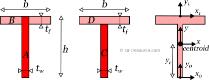
The moment of inertia of a tee section can be found if the total area is divided into two, smaller ones, A, B, as shown in figure below. Sub-area A consists of the entire web plus the part of the flange just above it, while sub-area B consists of the remaining flange part, having a width equal to b-tw. The final area, may be considered as the additive combination of A+B. Therefore, the moment of inertia Ix of the tee section, relative to non-centroidal x1-x1 axis, passing through the top edge, is determined like this:
where h the tee height, b the width of the flange, tf the thickness of the flange (parallel to x-x) and tw the thickness of the web (perpendicular to x-x).
Knowing Ix1, the moment of inertia Ix relative to centroidal x-x axis, can be determined using the Parallel Axes Theorem (see below). For this purpose, the distance between parallel axes x and x1 is needed. In other words, the location of the centroid must be determined. Its distance from the bottom edge of the tee is named yc in the figure below, however for this calculation we need its distance from the top edge, which should be h-yc. Using the first moments of area, of the sub-areas A,B, relative to axis x1, we find that:
where A is the area of the shape, equal to:
Therefore, the moment of inertia of the tee section, around its centroidal x axis can be found by application of the Parallel Axis Theorem, like this:
The moment of inertia Iy of the tee section, relative to centroidal y-y axis, can be found directly, by the additive combination of C+D sub-areas:
Parallel Axes Theorem
The moment of inertia of any shape, in respect to an arbitrary, non centroidal axis, can be found if its moment of inertia in respect to a centroidal axis, parallel to the first one, is known. The so-called Parallel Axes Theorem is given by the following equation:
where I' is the moment of inertia in respect to an arbitrary axis, I the moment of inertia in respect to a centroidal axis, parallel to the first one, d the distance between the two parallel axes and A the area of the shape, equal to , in the case of a tee.
For the product of inertia Ixy, the parallel axes theorem takes a similar form:
where Ixy is the product of inertia, relative to centroidal axes x,y (=0 for the double tee, due to symmetry), and Ixy' is the product of inertia, relative to axes that are parallel to centroidal x,y ones, having offsets from them and respectively.
Rotated axes
For the transformation of the moments of inertia from one system of axes x,y to another one u,v, rotated by an angle φ, the following equations are used:
where Ix, Iy the moments of inertia about the initial axes and Ixy the product of inertia. Iu, Iv and Iuv are the respective quantities for the rotated axes u,v. The product of inertia Ixy of a tee section, about centroidal x,y axes, is zero, because y is symmetry axis.
Principal axes
In principal axes, that are rotated by an angle θ relative to original centroidal ones x,y, the product of inertia becomes zero. Because of this, any symmetry axis of the shape, is also a principal axis. The moments of inertia about principal axes, are called principal moments of inertia, and are the maximum and minimum ones, for any angle of rotation of the coordinate system. For a tee section, y is a symmetry axis and therefore, x,y define the principal axes of the shape. As a result, Ix and Iy are the principal moments of inertia.
Dimensions
The dimensions of moment of inertia (second moment of area) are .
Mass moment of inertia
In Physics the term moment of inertia has a different meaning. It is related with the mass distribution of an object (or multiple objects) about an axis. This is different from the definition usually given in Engineering disciplines (also in this page) as a property of the area of a shape, commonly a cross-section, about the axis. The term second moment of area seems more accurate in this regard.
Applications
The moment of inertia (second moment or area) is used in beam theory to describe the rigidity of a beam against flexure (see beam bending theory). The bending moment M applied to a cross-section is related with its moment of inertia with the following equation:
where E is the Young's modulus, a property of the material, and κ the curvature of the beam due to the applied load. Beam curvature κ describes the extent of flexure in the beam and can be expressed in terms of beam deflection w(x) along longitudinal beam axis x, as: . Therefore, it can be seen from the former equation, that when a certain bending moment M is applied to a beam cross-section, the developed curvature is reversely proportional to the moment of inertia I. Integrating curvatures over beam length, the deflection, at some point along x-axis, should also be reversely proportional to I.